Q.No:1 JAM-2015
A Zener regulator has an input voltage in the range 15V-20V and a load current in the range of 5 mA-20 mA. If the Zener voltage is 6.8V, the value of the series resistor should be

(A)
\(390 \hspace{2mm} \Omega\)
(B)
\(420 \hspace{2mm} \Omega\)
(C)
\(440 \hspace{2mm} \Omega\)
(D)
\(460 \hspace{2mm} \Omega\)
Check Answer
Option A
Q.No: _ JAM-2015
In an experiment on charging of an initially uncharged capacitor, an RC circuit is made with the resistance \(R=10 \hspace{1mm}k\Omega\) and the capacitor \(C=1000\mu\)F along with a voltage source of 6V. The magnitude of the displacement current through the capacitor (in \(\mu\)A), 5 seconds after the charging
has started, is ___________________.
Check Answer
Ans- 360-370
Q.No:2 JAM-2015
In an ideal Op-Amp circuit shown below, \(R_1=3k\Omega\), \(R_1=1k\Omega\) and \(V_i=0.5\) sin \(\omega t\) (in Volt). Which of the following statements are true?
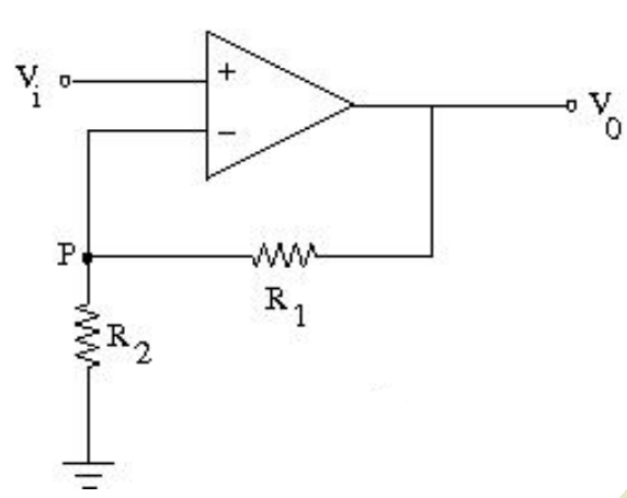
(A)
The current through \(R_1\)= The current through \(R_2\)
(B)
The potential at \(P\) is \(V_0 \frac{R_1}{R_2}\)
(C)
The amplitude of \(V_0\) is \(2V\)
(D)
The output voltage \(V_0\) is in phase with \(V_i\)
Check Answer
Option A,C,D
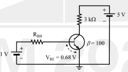
Q.No:3 JAM-2015
In the given circuit, \(V_{cc}=10V\) and \(\beta=100\) for the n-p-n transistor. The collector voltage \(V_c\) (in
Volts) is __________.
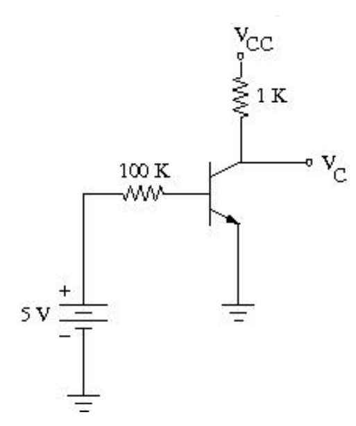
Check Answer
Ans 5.5-5.9
Q.No:4 JAM-2015
A diode at room temperature \(kT=0.025\)eV with a current of \(1\mu\)A has a forward bias voltage \(V_F=0.4\)V. For \(V_F=0.4\)V, the value of the diode current (in \(\mu\)A) is _____________.
Check Answer
Ans 53-57
Q.No:5 JAM-2016
The phase difference \((\delta)\) between input and output voltage for the following circuits (i) and (ii)

will be
(A)
\(0\) and \(0\)
(B)
\(\pi/2\) and \(0<\delta \leq \pi/2\) respectively.
(C)
\(\pi/2\) and \(\pi/2\)
(D)
\(0\) and \(0<\delta \leq \pi/2\) respectively.
Check Answer
Option D
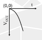
Q.No:6 JAM-2016
If a constant voltage \(+V\) is applied to the input of the following OPAMP circuit for a time t, then the output voltage \(V_0\) will approach

(A)
\(+V\) exponentially.
(B)
-\(V\) exponentially.
(C)
\(+V\) linearly.
(D)
-\(V\) linearly.
Check Answer
Option D
Q.No:7 JAM-2016
In the following RC network, for an input signal frequency \(f=\frac{1}{2\pi R C}\), the voltage gain \(|\frac{v_0}{v_i}|\) and the phase angle \(\varphi\) between \(v_0\) and \(v_i\) respectively are

(A)
\(\frac{1}{2}\) and \(0\)
(B)
\(\frac{1}{3}\) and \(0\)
(C)
\(\frac{1}{2}\) and \(\frac{\pi}{2}\)
(D)
\(\frac{1}{3}\) and \(\frac{\pi}{2}\)
Check Answer
Option B
Q.No:8 JAM-2016
The output voltage \(V_0\) of the OPAMP circuit given below is ____________ .

Check Answer
Ans 6
Q.No:9 JAM-2016
In the circuit given below, the collector to emitter voltage \(V_{CE}\) is ____________ V.
(Neglect \(V_{BE}\), take \(\beta=100\))
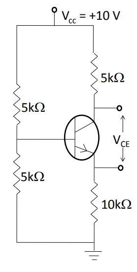
Check Answer
Ans 2-3
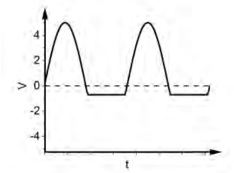
Q.No:10 JAM-2017
Consider the following circuit with two identical \(Si\) diodes. The input ac voltage waveform has the peak voltage \(V_p=2V\) as shown,
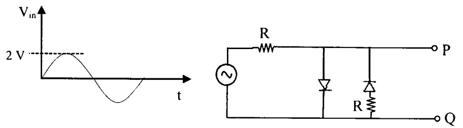
The voltage waveform across PQ will be represented by:
Check Answer
Option C
Q.No:11 JAM-2017
An n-p-n transistor is connected in a circuit as shown in the figure. If \(I_c=1\)mA,\(\beta=50\), \(V_{BE}=0.7V\) and the current through \(R_2\) is \(10I_B\) where \(I_B\) is the base
current. Then the ratio \(R_1/R_2\) is :

(A)
0.375
(B)
0.25
(C)
0.5
(D)
0.275
Check Answer
Option MTA
Q.No:12 JAM-2017
An OPAMP is connected in a circuit with a Zener diode as shown in the figure. The value of resistance R in \(k\Omega\) for obtaining a regulated output \(V_0=9V\) is
(Specify your answer to two digits after the decimal point)
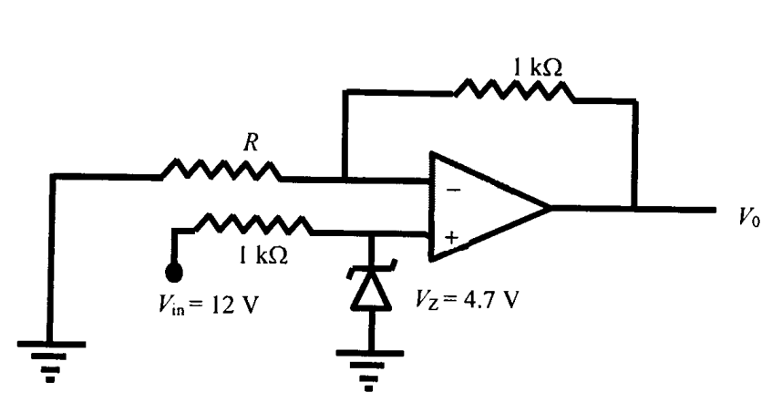
Check Answer
Ans 1.05-1.15
Q.No:13 JAM-2018
Which one of the following graphs shows the correct variation of \(v_0\) with \(v_i\) ? Here, \(v_d\) is the voltage
drop across the diode and the Op-Amp is assumed to be ideal.
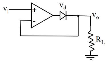

Check Answer
Option A
Q.No:14 JAM-2018
For the given circuit, value of the base current \((I_b)\) of the npn transistor will be ____________mA. (\(\beta\) is
the current gain and assume Op-Amp as ideal.)
(Specify your answer in mA upto two digits after the decimal point.)

Check Answer
Ans 0.09-0.11
Q.No:15 JAM-2018
For the following circuit, the collector voltage with respect to ground will be ____________ V. (Emitter
diode voltage is 0.7 V and \(\beta_{DC}\) of the transistor is large.)
(Specify your answer in volts upto one digit after the decimal point.)

Check Answer
Ans 2.9-3.5
Q.No:16 JAM-2018
In the following circuit, the time constant RC is much greater than the period of the input signal. Assume diode as ideal and resistance \(R\) to be large. The dc output voltage across resistance \(R\) will be _____________ V.
(Specify your answer in volts upto one digit after the decimal point.)
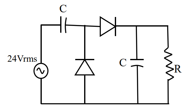
Check Answer
Ans 66-69
Q.No:17 JAM-2019
For using a transistor as an amplifier, choose the correct option regarding the resistances of base-emitter \((R_{BE})\) and base-collector \((R_{BC})\) junctions
(A)
Both \(R_{BE}\) and \(R_{BC}\) are very low
(B)
Very low \(R_{BE}\) and very high \(R_{BC}\)
(C)
Very high \(R_{BE}\) and very low \(R_{BC}\)
(D)
Both \(R_{BE}\) and \(R_{BC}\) are very high
Check Answer
Option B
Q.No:18 JAM-2019
For the input voltage \(V_i=(200mV)\) \(sin 400t\), the amplitude of the output voltage \((V_0)\) of
the given OPAMP circuit is ___________ V.
(Round off to 2 decimal places)

Check Answer
Ans 11.00-11.03
Q.No:19 JAM-2019
The value of emitter current in the given circuit is _________ \(\mu\)A.
(Round off to 1 decimal place)

Check Answer
Ans 444.8-450.0
Q.No:20 JAM-2019
The Zener current \(I_Z\) for the given circuit is ________________ mA.

Check Answer
Ans 1
Q.No:21 JAM-2020
In the circuit shown in the figure, both OPAMPs are ideal. The output for the circuit \(V_{out}\) is

(A)
\(20V_1\) + \(10V_2\)
(B)
\(-20V_1\) + \(10V_2\)
(C)
\(10V_1\) - \(20V_2\)
(D)
\(20V_1\) - \(10V_2\)
Check Answer
Option A
Q.No:22 JAM-2020
The figure shows a circuit containing two diodes \(D_1\) and \(D_2\) with threshold voltages \(V_{TH}\) of 0.7 V and 0.3 V, respectively. Considering the simplified diode model, which assumes diode I-V
characteristic as shown in the plot on the right, the current through the resistor \(R\) is _________________ \(\mu\)A.
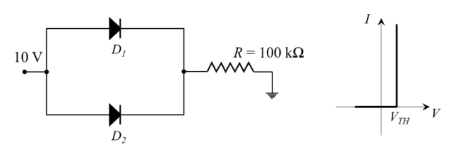
Check Answer
Ans 97
Q.No:23 JAM-2020
For the ac circuit shown in the figure, \(R=100 \hspace{2mm} k\Omega\) and \(C=10\)pF, the phase difference between \(V_{in}\) and \(V_{out}\) is \(90^\circ\) at the input signal frequency of _______________ kHz.
(Round off to 2 decimal places)
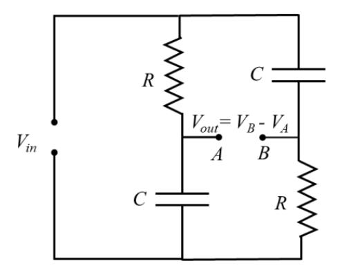
Check Answer
Ans 159.0-159.3
Q.No:24 JAM-2020
In the transistor circuit given in the figure, the emitter-base junction has a voltage drop of 0.7 V. A collector-emitter voltage of 14 V reverse biases the collector. Assuming the collector current to be the same as the emitter current, the value of \(R_B\) is ___________________ \(k\Omega\).
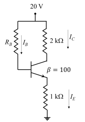
Check Answer
Ans 860-875
Q.No:25 JAM-2021
For the given circuit, \(V_D\) is the threshold voltage of the diode. The graph that best depicts the variation of \(V_0\) with \(V_i\) is


Check Answer
Option A
Q.No:26 JAM-2021
For the given circuit, identify the correct statement(s).

(A)
\(I_0=1\) mA
(B)
\(V_0=3\) V
(C)
If \(R_L\) is doubled, \(I_0\) will change to 0.5 mA
(D)
If \(R_L\) is doubled, \(V_0\) will change to 6 V
Check Answer
Option A,B,D
Q.No:27 JAM-2021
The following Zener diode voltage regulator circuit is used to obtain 20 V regulated output at load resistance \(R_L\) from a 35 V dc power supply. Zener diodes are rated at 5W and 10V. The value of the resistance \(R\) is _________________ \(\Omega\).
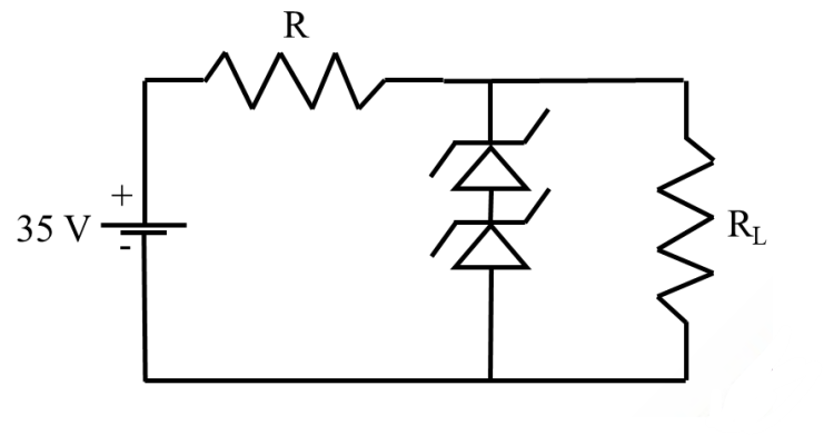
Check Answer
Ans 30
Q.No:28 JAM-2022
For the given circuit, \(R=125\Omega\), \(R_L=470\Omega\),
\(V_z=9\)V and \(I_z ^{max}=65\)mA. The minimum and maximum values of the input voltage (\(V_i ^{min}\) and \(V_i ^{max}\)) for which the Zener diode will be in the ‘ON’ state are

(A)
\(V_i ^{min}=9.0\) V and \(V_i ^{max}=11.4\) V
(B)
\(V_i ^{min}=9.0\) V and \(V_i ^{max}=19.5\) V
(C)
\(V_i ^{min}=11.4\) V and \(V_i ^{max}=15.5\) V
(D)
\(V_i ^{min}=11.4\) V and \(V_i ^{max}=19.5\) V
Check Answer
Option D
Q.No:29 JAM-2022
For the given operational amplifier circuit \(R_1=120\Omega , R_2=1.5 k\Omega\) and \(V_S=0.6\)V, then the output current \(I_0\) is _________________ mA.

Check Answer
Ans 5
Q.No:30 JAM-2023
For the following circuit, choose the correct waveform corresponding to the output signal \((V_{out})\). Given \(V_{in}\) = 5 sin(200 \(\pi t\)) V, forward bias voltage of the diodes (D and Z) = 0.7 V and reverse Zener voltage = 3 V.


Check Answer
Option A
Q.No:31 JAM-2023
In the given circuit, with an ideal op-amp for what value of \(\frac{R_1}{R_2}\) the output of the amplifier \(V_{out}=V_2-V_1\)?

A) \(1\)
B) \(1/2\)
c) \(2\)
D) \(3/2\)
Check Answer
Option A
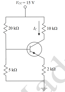
Q.No:32 JAM-2023
In the circuit shown, assuming the current gain \(\beta\)= 100 and \(V_{BE}\)= 0.7 V, what will be the collector voltage \(V_C\) in \(V\)?
Given: \(V_{CC}\)= 15 V, \(R_1\)= 100 k\(\Omega\), \(R_2\)= 50 k\(\Omega\), \(R_C\)= 4.7 k\(\Omega\), and \(R_E\)= 3.3 k\(\Omega\)
A) 8.9
B) 5.1
C) 4.3
D) 3.2
Check Answer
Ans MTA
Q.No:33 JAM-2023
Two silicon diodes are connected to a battery and two resistors as shown in the figure. The current through the battery is _________ A
(rounded off to two decimal places).

Given: The forward voltage drop across each diode = 0.7 V
Check Answer
Ans 0.43
Q.No:34 JAM-2024
In the following OP-AMP circuit, \( v_{\text{in}} \) and \( v_{\text{out}} \) represent the input and output signals, respectively.

Choose the correct statement(s):
A) \( v_{\text{out}} \) is out-of-phase with \( v_{\text{in}} \)
B) Gain is unity when \( R_1 = R_2 \)
C) \( v_{\text{out}} \) is in-phase with \( v_{\text{in}} \)
D) \( v_{\text{out}} \) is zero
Check Answer
Option A,B
Q.No:35 JAM-2024
A Zener diode (rating \( 10V, 2W \)) and a normal diode (turn-on voltage \( 0.7V \)) are connected in a circuit as shown in the figure. The voltage drop \( V_L \) across the \( 2k\Omega \) resistance is _____ V. (Rounded off to one decimal place)

Check Answer
Ans 6.2
Q.No:36 JAM-2024
A transistor (\( \beta = 100, V_{BE} = 0.7V \)) is connected as shown in the circuit below.
\( V_{CC} = 15 V \)
The current \( I_C \) will be _____ mA. (Rounded off to two decimal places)
Check Answer
Ans 1.10-1.15
Q.No:37 JAM-2025
If the input voltage waveform \(V_{\text{IN}}\) is a ramp function
(as shown in the \(V_{\text{IN}}-t\) plot), then the output waveform
(\(V_{\text{OUT}}\)) for the given circuit diagram having an ideal
operational amplifier (Op-Amp) is
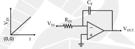
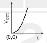
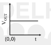
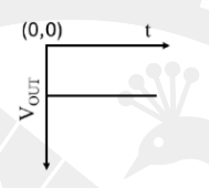
Check Answer
Option D
Q.No:38 JAM-2025
In the circuit given below, the frequency of the input voltage \(V_{\text{IN}}\)
is \(\omega = 10^4\ \text{rad/s}\).
The output voltage \(V_{AB}\) leads \(V_{\text{IN}}\) by

A) \(0^\circ \)
B) \(45^\circ \)
C) \(90^\circ \)
D) \(-90^\circ \)
Check Answer
Option C
Q.No:39 JAM-2025
An ideal p–n junction diode (ideality factor \(\eta\) = 1) is operating in forward
bias at room temperature (thermal energy = 26 meV).
If the diode current is 26 mA for an applied bias of 1.0 V, the dynamic
resistance (\(r_{ac}\)) is ______ \(\Omega\). (up to two decimal places)
Check Answer
ANS 0.95 to 1.05
Q.No:40 JAM-2025
An NPN bipolar junction transistor (BJT) is connected in common emitter (CE)
configuration as shown in the circuit diagram.
The amplifier is operating in the saturation regime.
The collector–emitter saturation voltage \(V_{CE(\text{sat})}\) is 0.2 V.
The current gain \(\beta = 100\).
The maximum value of base resistance \(R_{BB}\) is ______ \(k\Omega\). (in integer)
Check Answer
ANS 20
Q.No:41 JAM-2025
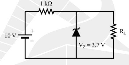
For a Zener diode as shown in the circuit diagram below, the Zener voltage
\(V_Z\) is 3.7 V.
For a load resistance (\(R_L\)) of 1 \(k\Omega\), a current \(I_1\) flows through the
load. If \(R_L\) is decreased to 500 \(\Omega\), the current changes to \(I_2\).
The ratio
\[
\frac{I_2}{I_1}
\]
is ______. (up to two decimal places)