Q.No:1 CSIR Dec-2014
A large MOS transistor consists of \(N\) individual transistors connected in parallel. If the only form of noise in each transistor is \(1/f\) noise, then the equivalent voltage noise spectral density for the MOS transistor is
(1)
\(1/N\) times that of a single transistor
(2)
\(1/N^2\) times that of a single transistor
(3)
\(N\) times that of a single transistor
(4)
\(N^2\) times that of a single transistor
Check Answer
Option 1
Q.No:2 CSIR Dec-2014
Consider a Low Pass (LP) and a High Pass (HP) filter with cut-off frequencies \(f_{LP}\) and \(f_{HP}\), respectively, connected in series or in parallel configurations as shown in the Figures A and B below.

Which of the following statements is correct?
(1)
For \(f_{HP}<f_{LP}\), A acts as a Band Pass filter and B acts as a Band Reject filter
(2)
For \(f_{HP}>f_{LP}\), A stops the signal from passing through and B passes the signal without filtering
(3)
For \(f_{HP}<f_{LP}\), A acts as a Band Pass filter and B passes the signal without filtering
(4)
For \(f_{HP}>f_{LP}\), A passes the signal without filtering and B acts as a Band Reject filter
Check Answer
Option 3
Q.No:3 CSIR Dec-2014
The power density of sunlight incident on a solar cell is \(100 mW/cm^2\). Its short circuit current density is \(30 mA/cm^2\) and the open circuit voltage is \(0.7 V\). If the fill factor of the solar cell decreases from \(0.8\) to \(0.5\) then the percentage efficiency will decrease from
(1)
\(42.0\) to \(26.2\)
(2)
\(24.0\) to \(16.8\)
(3)
\(21.0\) to \(10.5\)
(4)
\(16.8\) to \(10.5\)
Check Answer
Option 4
Q.No:4 CSIR Dec-2015
Two data sets A and B consist of \(60\) and \(10\) readings of a voltage measured using voltmeters of resolution of \(1 \text{ mV}\) and \(0.5 \text{ mV}\) respectively. The uncertainty in the mean voltage obtained from the data sets A and B are \(\text{U}_{\text{A}}\) and \(\text{U}_{\text{B}}\), respectively. If the uncertainty of the mean of the combined data sets is \(\text{U}_{\text{AB}}\), then which of the following statements is correct?
(1)
\(\text{U}_{\text{AB}} \text{U}_{\text{B}}\)
(2)
\(\text{U}_{\text{AB}}< \text{U}_{\text{A}}\) and \(\text{U}_{\text{AB}}< \text{U}_{\text{B}}\)
(3)
\(\text{U}_{\text{AB}}> \text{U}_{\text{A}}\) and \(\text{U}_{\text{AB}}< \text{U}_{\text{B}}\)
(4)
\(\text{U}_{\text{AB}}> \text{U}_{\text{A}}\) and \(\text{U}_{\text{AB}}> \text{U}_{\text{B}}\)
Check Answer
Option 2
Q.No:5 CSIR June-2016
The dependence of current \(I\) on the voltage \(V\) of a certain device is given by
\[
I=I_0\left(1-\frac{V}{V_0}\right)^2
\]
where \(I_0\) and \(V_0\) are constants. In an experiment the current \(I\) is measured as the voltage \(V\) applied across the device is increased. The parameters \(V_0\) and \(\sqrt{I_0}\) can be graphically determined as
(1)
the slope and the \(y\)-intercept of the \(I\)-\(V^2\) graph
(2)
the negative of the ratio of the \(y\)-intercept and the slope, and the \(y\)-intercept of the \(I\)-\(V^2\) graph
(3)
the slope and the \(y\)-intercept of the \(\sqrt{I}\)-\(V\) graph
(4)
the negative of the ratio of the \(y\)-intercept and the slope, and the \(y\)-intercept of the \(\sqrt{I}\)-\(V\) graph
Check Answer
Option 4
Q.No:6 CSIR Dec-2016
Two sinusoidal signals are sent to an analog multiplier of scale factor \(1 V^{-1}\) followed by a low pass filter (LPF).
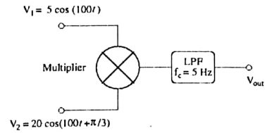
If the roll-off frequency of the LPF is \(f_c=5 Hz\), the output voltage \(V_{\text{out}}\) is
(1)
\(5 V\)
(2)
\(100 V\)
(3)
\(25 V\)
(4)
\(50 V\)
Check Answer
Option 2
Q.No:7 CSIR June-2018
Two signals \(A_1 \sin{(\omega t)}\) and \(A_2 \cos{(\omega t)}\) are fed into the input and the reference channels, respectively, of a lock-in amplifier. The amplitude of each signal is \(1 V\). The time constant of the lock-in amplifier is such that any signal of frequency larger than \(\omega\) is filtered out. The output of the lock-in amplifier is
(1)
\(2 V\)
(2)
\(1 V\)
(3)
\(0.5 V\)
(4)
\(0 V\)
Check Answer
Option 4
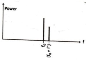
Q.No:8 CSIR Dec-2018
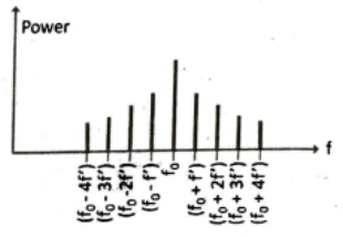
The amplitude of a carrier signal of frequency \(f_0\) is sinusoidally modulated at a frequency \(f'\ll f_0\). Which of the following graphs best describes its power spectrum?


Check Answer
Option 2
Q.No:9 CSIR June-2019
In the following circuit, each device \(D\) may be an insulator with probability \(p\), or a conductor with probability \((1-p)\).
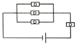
The probability that a non-zero current flows through the circuit is
(1)
\(2-p-p^3\)
(2)
\((1-p)^4\)
(3)
\((1-p)^2 p^2\)
(4)
\((1-p)(1-p^3)\)
Check Answer
Option 4
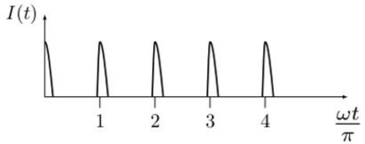
Q.No:10 CSIR June-2019
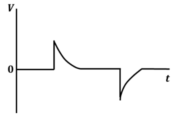
An ac signal of the type as shown in the figure, is applied across a resistor \(R=1 \Omega\).

The power dissipated across the resistor is
(1)
\(12.5 W\)
(2)
\(9 W\)
(3)
\(25 W\)
(4)
\(21.5 W\)
Check Answer
Option 4
Q.No:11 CSIR June-2019
For optimal performance of an op-amp based current-to-voltage converter circuit, the input and output impedance should be
(1)
low input impedance and high output impedance
(2)
low input impedance and low output impedance
(3)
high input impedance and high output impedance
(4)
high input impedance and low output impedance
Check Answer
Option 2
Q.No:12 CSIR Dec-2019
Assume that the noise spectral density, at any given frequency, in a current amplifier is independent of frequency. The bandwidth of measurement is changed from \(1 Hz\) to \(10 Hz\). The ratio A/B of the RMS noise current before (A) and after (B) the bandwidth modification is
(1)
\(1/10\)
(2)
\(1/\sqrt{10}\)
(3)
\(\sqrt{10}\)
(4)
\(10\)
Check Answer
Option 2
Q.No:13 CSIR June-2020
An inductor \(L\), a capacitor \(C\) and a resistor \(R\) are connected in series to an AC source, \(V=V_0\sin{\omega t}\). If the net current is found to depend only on \(R\), then
(a)
\(C=0\)
(b)
\(L=0\)
(c)
\(\omega=1/\sqrt{LC}\)
(d)
\(\omega=\sqrt{\frac{1}{LC}-\frac{R^2}{4L^2}}\)
Check Answer
Option c
Q.No:14 CSIR June-2020
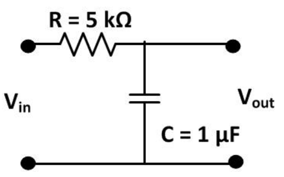
A \(10 V\) battery is connected in series to a resistor \(R\) and a capacitor \(C\), as shown the figure.

The initial charge on the capacitor is zero. The switch is turned on and the capacitor is allowed to charge to its full capacity. The total work done by the battery in this process is
(a)
\(10^{-3} J\)
(b)
\(2\times 10^{-3} J\)
(c)
\(5\times 10^{-4} J\)
(d)
\(47\times 10^{-2} J\)
Check Answer
Option a
Q.No:15 CSIR Feb-2022
In the LCR circuit shown below, the resistance \(R=0.05\Omega\) , the inductance \(L=1H\) and
the capacitance \(C=0.04F\) .

If the input \(v_{in}\) is a square wave of angular frequency 1rad/s, the output \(v_{out}\) is best
approximated by a
(1)
Square wave of angular frequency 1rad/s
(2)
Sine wave of angular frequency 1rad/s
(3)
Square wave of angular frequency 5rad/s
(4)
Sine wave of angular frequency 5rad/s
Check Answer
Option 4
Q.No:16 CSIR Sep-2022
A high frequency voltage signal \(v_i=v_m sin \hspace{1mm}\omega t\) is applied to a parallel plate deflector as shown in the figure.

An electron beam is passing through the deflector along the central line. The best qualitative representation of the intensity \(I(t)\) of the beam after it goes through the narrow circular aperture \(D\), is


Check Answer
Option 1
Q.No:17 CSIR Sep-2022
A receiver operating at 27° C has an input resistance of 100\(\Omega\). The input thermal noise voltage for this receiver with a bandwidth of 100 kHz is closest to
(1)
0.4 nV
(2)
0.6 pV
(3)
40 mV
(4)
\(0.4 \mu V\)
Check Answer
Option 4
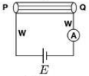
Q.No:18 CSIR june-2023
A circuit needs to be designed to measure the resistance \(R\) of a cylinder \(PQ\) to the best possible accuracy, using an ammeter \(A\), a voltmeter \(V\), a battery \(E\) and a current source \(I_s\) (all assumed to be ideal). The value of \(R\) is known to be approximately \(10 \hspace{1mm}\Omega\), and the resistance W of each of the connecting wires is close to \(10 \hspace{1mm}\Omega\). If the current from the current source and voltage from the battery are known exactly, which of the following circuits provides the most accurate measurement of \(R\)?


1) (b)
2) (a)
3) (d)
4) (c)
Check Answer
Option 2
Q.No:19 CSIR june-2024
In the circuit shown in the figure, the resistances \(R\) and \(R'\) change due to strain. While \(R\) increases, \(R'\) decreases by the same amount \(\Delta R\) due to the applied strain. The unstrained values of \(R\) and \(R'\) are \(100 \, \Omega\) each. If same strain is applied to all the resistors, and the output voltage \((V_{ab})\) changes to \(0.3 \, \text{V}\), then \(\Delta R\) is closest to

1) \(3 \, \Omega\)
2) \(1.5 \, \Omega\)
3) \(4.5 \, \Omega\)
4) \(6 \, \Omega\)
Check Answer
Option 1
Q.No:19 CSIR june-2024
A battery with an open circuit voltage of 10 V is connected to a load resistor of 485 \(\Omega\) and the voltage measured across the battery terminals using an ideal voltmeter is 9.7 V. The internal resistance of the battery is closest to
1) 30 \(\Omega\)
2) 15 \(\Omega\)
3) 20 \(\Omega\)
4) 40 \(\Omega\)
Check Answer
Option 2
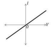
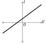
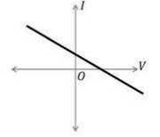
Q.No:20 CSIR Dec-2024
A circuit component consists of a resistor in parallel with an ideal current source.
The I–V characteristics of the component were measured using a variable voltage
source and an ammeter ‘A’, as shown in the figure.
The arrow in the figure indicates the positive direction of current.
The I–V characteristics of the component is best represented by


Check Answer
Option 2
Q.No:21 CSIR Dec-2024
An ideal inductor \(L\) is connected in series to a \(150\,\Omega\) resistor as shown
in the circuit (inset). When the circuit is driven by a battery \(B_1\), the voltage
across the resistor as a function of time, as measured by an oscilloscope, is shown
in the plot.
Based on this observation, the estimated value of \(L\) is closest to

1) 50 mH
2) 300 mH
3) 450 mH
4) 150 mH
Check Answer
Option 4
Q.No:22 CSIR June-2025
Consider the device \(D\) shown in the figure. Its current–voltage characteristic
is given by
\[
I = aV + bV^2,
\]
where \(I\) is the current, \(V\) is the input voltage, and \(a\) and \(b\) are constants.
The device is used to mix a voltage signal
\[
V = V_{DC} + V_{AC},
\qquad
V_{AC} = V_0 \cos \omega t,
\]
where \(V_{DC}\) and \(V_0\) are constants.
The frequency components present in the current \(I\) are

1) \(0\) and \(\omega\)
2) \(0,\ \omega,\ \text{and } 2\omega\)
3) \(0\) and \(2\omega\)
4) \(\omega\) and \(2\omega\)
Check Answer
Option 2
Q.No:23 CSIR June-2025
Let \(R_A\) and \(R_B\) be the resistances of a channel determined (by taking the ratio
of the voltage measured and current flowing) using configurations A and B respectively,
as shown in the figure.
In both configurations:
• Each lead resistance is \(5~\Omega\)
• Each contact resistance is \(10~\Omega\)
• The channel has a resistivity of \(20~\Omega/\text{mm}\)
• Voltmeter and current source are ideal
The ratio \(R_B/R_A\) is


1) 1.1
2) 1.2
3) 1.3
4) 1.5
Check Answer
Option 3
Q.No:1 GATE-2013
A voltage regulator has ripple rejection of \(-50 dB\). If input ripple is \(1 mV\), what is the output ripple voltage in \(\mu V\)? The answer should be up to two decimal places. ________________
Check Answer
Ans 3.16
Q.No:2 GATE-2019
A 3-bit analog-to-digital converter is designed to digitize analog signals ranging from \(0 V\) to \(10 V\). For this converter, the binary output corresponding to an input of \(6 V\) is
(A)
011
(B)
101
(C)
100
(D)
010
Check Answer
Option C
Q.No:3 GATE-2019
For a given load resistance \(R_L=4.7 ohm\), the power transfer efficiencies \(\left(\eta=\frac{P_{\text{load}}}{P_{\text{total}}}\right)\) of a dc voltage source and a dc current source with internal resistances \(R_1\) and \(R_2\), respectively, are equal. The product \(R_1 R_2\) in units of \(ohm^2\) (rounded off to one decimal place) is ___________
Check Answer
Ans 22.0-22.2
Q.No:4 GATE-2022
A power supply has internal resistance \(R_S\) and open load voltage \(V_S=5 \hspace{1mm}\text{V}\). When a load resistance \(R_L\) is connected to the power supply, a voltage drop of \(V_L=4\hspace{1mm}\text{V}\) is measured across the load. The value of \(\frac{R_L}{R_S}\) is ___________ (Round off to the nearest integer)
Check Answer
Ans 4
Q.No:5 GATE-2023
An input voltage in the form of a square wave of frequency 1 kHz is given to a circuit, which results in the output shown schematically below. Which one of the following options is the CORRECT representation of the circuit?