Q.No:1 JEST-2012
A capacitor \(C\) is connected to a battery \(V_0\) through three equal resistors \(R\) and a switch \(S\) as shown below:

The capacitor is initially uncharged. At time \(t=0\), the switch \(S\) is closed. The voltage across the capacitor as a function of time \(t\) for \(t>0\) is given by
(a)
\((V_0/2)(1-\exp{(-t/2RC)})\)
(b)
\((V_0/3)(1-\exp{(-t/3RC)})\)
(c)
\((V_0/3)(1-\exp{(-3t/2RC)})\)
(d)
\((V_0/2)(1-\exp{(-2t/3RC)})\)
Check Answer
Option d
Q.No:2 JEST-2012
The ratio of maximum to minimum resistance that can be obtained with \(N\) \(1\)-\(\Omega\) resistors is
(a)
\(N\)
(b)
\(N^2\)
(c)
\(1\)
(d)
\(\infty\)
Check Answer
Option b
Q.No:3 JEST-2014
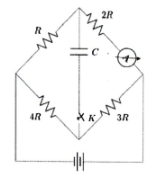
Find the resonance frequency (rad/sec) of the circuit shown in the figure below

(a)
\(1.41\)
(b)
\(1.0\)
(c)
\(2.0\)
(d)
\(1.73\)
Check Answer
Option b
Q.No:4 JEST-2016
It is found that when the resistance \(R\) indicated in the figure below is changed from \(1 k\Omega\) to \(10 k\Omega\), the current flowing through the resistance \(R'\) does not change. What is the value of the resistor \(R'\)?

(A)
\(5 k\Omega\)
(B)
\(100 \Omega\)
(C)
\(10 k\Omega\)
(D)
\(1 k\Omega\)
Check Answer
Option B
Q.No:5 JEST-2017
Consider the following circuit in steady state condition. Calculate the amount of charge stored in \(1 \mu F\) and \(2 \mu F\) capacitors respectively.

(A)
\(4 \mu C\) and \(8 \mu C\)
(B)
\(8 \mu C\) and \(4 \mu C\)
(C)
\(3 \mu C\) and \(6 \mu C\)
(D)
\(6 \mu C\) and \(3 \mu C\)
Check Answer
Option A
Q.No:6 JEST-2017
For the circuit shown below, what is the ratio \(\frac{I_1}{I_2}\)?

Check Answer
Ans 16
Q.No:7 JEST-2018
In the circuit shown below, the capacitor is initially uncharged. Immediately after the
key \(K\) is closed, the reading in the ammeter is \(27 mA\). What will the reading (in mA) be a long time later?
Check Answer
Ans 9555
Q.No:8 JEST-2019
A dc voltage of \(80\) Volt is switched on across a circuit containing a resistance of \(5 \Omega\) in series with an inductance of \(20H\). What is the rate of change of current at the instant when the current is \(12 A\)?
(A)
\(0 A/s\)
(B)
\(1 A/s\)
(C)
\(5 A/s\)
(D)
\(80 A/s\)
Check Answer
Option B
Q.No:9 JEST-2020
The ratio of maximum to minimum resistance that can be obtained with \(N\) number of \(3\)-\(\Omega\) resistors is
(A)
\(N\)
(B)
\(N^2\)
(C)
\(N^3\)
(D)
\(N^4\)
Check Answer
Option B
Q.No:10 JEST-2020
What is the charge stored on each capacitor \(C_1\) and \(C_2\) in the circuit shown in the given figure?

(A)
\(6 \mu C, 6 \mu C\)
(B)
\(6 \mu C, 3 \mu C\)
(C)
\(3 \mu C, 6 \mu C\)
(D)
\(3 \mu C, 3 \mu C\)
Check Answer
Option A
Q.No:11 JEST-2023
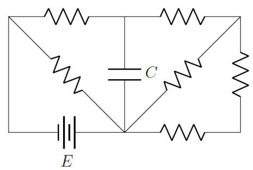
Consider the circuit shown in the figure below. \(C\) is the capacitance of the capacitor, \(E\) is the voltage provided by the battery and all the resistors are identical. What is the charge stored in the capacitor in units of \(CE\), once it is fully charged.
(a) \(\frac{3}{4}\)
(b) \(\frac{5}{8}\)
(c) \(\frac{3}{8}\)
(d) \(\frac{5}{4}\)
Check Answer
Option b
Q.No:12 JEST-2025
A capacitor with capacitance \(C\) is connected in series with a resistor of resistance
\(R\) and an ideal DC source with voltage \(V_s\).
At one instant during the charging of the capacitor, if the resistor is replaced by
a wire of zero resistance, which of the following statements is true?
a) The capacitor immediately attains the source voltage \(V_s\).
b) The voltage across the capacitor will increase slowly.
c) None of the others is true.
d) The voltage across the capacitor will drop immediately to zero.
Check Answer
Option a
Q.No:13 JEST-2025
If a resistor of \(10~\text{k}\Omega\) and a capacitor of \(0.5~\mu\text{F}\) are connected
in series across an AC supply of \(220~\text{V}\) (rms) at \(50~\text{Hz}\),
what is the average power (in mW, to the nearest integer) dissipated in the circuit?
Check Answer
ANS 3444
Q.No:1 TIFR-2014
In the following circuit, the AC source is an ideal voltage source. What is the amplitude of the steady state current through the inductor at resonance?

(a)
\(V_0\sqrt{C/L}\)
(b)
\(V_0/R\)
(c)
\(V_0\sqrt{C/(R^2 C+2L)}\)
(d)
zero
Check Answer
Option a
Q.No:2 TIFR-2015
Two LCR circuits (A) and (B) are shown below where \(C_C\ll C\). At time \(t=0\), a charge \(Q\) is put on the capacitor \(C\).

Which of the following statements is correct?
(a)
The charge \(Q\) will decay faster in (A)
(b)
The charge \(Q\) will decay faster in (B)
(c)
The charge \(Q\) will decay at the same rate in (A) and (B)
(d)
The relative decay rates cannot be predicted without knowing the exact values of \(L, C, R\) and \(C_C\)
Check Answer
Option a
Q.No:3 TIFR-2015
You are given the following circuit and two instruments: a voltmeter and an ammeter both with \(0.001\%\) accuracy in their readings.

Which of the following methods will result in the most accurate reading for the current without interrupting the current in the circuit?
(a)
Use voltmeter to measure voltage across points B and C
(b)
Use the ammeter to measure current at point B
(c)
Use voltmeter to measure voltage across points A and B
(d)
Use voltmeter to measure voltage across points A and C
Check Answer
Option c
Q.No:4 TIFR-2016
A student in the laboratory is provided with a bunch of standard resistors as well as the following instruments

Using this equipment (and nothing else), the student is expected to measure the resistance \(R\) of one of the given resistors. The least accurate result would be obtained by
(a)
measuring the Joule heating.
(b)
passing a constant current and measuring the voltage across it.
(c)
measuring the current on application of a constant voltage across it.
(d)
the Wheatstone bridge method.
Check Answer
Option a
Q.No:5 TIFR-2016
Consider a sawtooth waveform which rises linearly from \(0 Volt\) to \(1 Volt\) in \(10 ns\) and then decays linearly to \(0 V\) over a period of \(100 ns\). Find the r.m.s. voltage in units of milliVolt?
Check Answer
Ans 577
Q.No:6 TIFR-2016
The circuit shown below contains an unknown device \(X\).

The current-voltage characteristics of the device \(X\) were determined and are shown in the plot given below.

Determine the current \(I\) (in mA) flowing through the device \(X\).
Check Answer
Ans 12
Q.No:7 TIFR-2017
A current source produces a square wave \(I(t)\) of \(1.0 \hspace{1mm}\text{V}\) peak-to-peak voltage and is used to drive the RC circuit shown below.

Which of the following represents the correct voltage across the capacitor C?

Check Answer
Option d
Q.No:8 TIFR-2017
A signal is to be sent from a coaxial cable with impedance \(40 \hspace{1mm}\Omega\) into a second coaxial cable with impedance \(60 \hspace{1mm}\Omega\). We can prevent reflection at the joint between the cables, by adding an impedance in parallel to the second cable. What should be the value, in units of Ohms (\(\Omega\)), of that impedance?
Check Answer
Ans 120
Q.No:9 TIFR-2017
An AC voltage source has an internal resistance of \(50 \hspace{1mm}\Omega\) and is specified to deliver an rms voltage of \(50 \hspace{1mm}\text{V}\) to a matched load. If you connect this AC source to a cathode-ray oscilloscope with \(1 \hspace{1mm}\text{M}\Omega\) input setting, what will be the peak-to-peak voltage you observe?
Check Answer
Ans 283
Q.No:10 TIFR-2018
The figure below shows an unknown circuit, with an input and output voltage signal.

From the form of the input and output signals, one can infer that the circuit is likely to be
Check Answer
Option b
Q.No:11 TIFR-2018
A realistic voltmeter can be modelled as an ideal voltmeter with an input resistor in parallel as shown below:

Such a realistic voltmeter, with input resistance \(1 \hspace{1mm} k\Omega\), gives a reading of \(100 \hspace{1mm} {mV}\) when connected to a voltage source with source resistance \(50 \hspace{1mm} \Omega\). What will a similar voltmeter, with input resistance \(1 \hspace{1mm} \text{M}\Omega\), read in \(\text{mV}\), when connected to the same voltage source?
Check Answer
Ans 105
Q.No:12 TIFR-2018
The current \(i\) flowing through the following circuit is

(a)
\(0.5 \hspace{1mm} \text{A}\)
(b)
\(0.6 \hspace{1mm} \text{A}\)
(c)
\(0.75 \hspace{1mm} \text{A}\)
(d)
\(1.0 \hspace{1mm} \text{A}\)
Check Answer
Option c
Q.No:13 TIFR-2018
Which one of the following circuits, constructed only with resistors and voltmeters, will allow you to obtain the correct value of resistance \(r_s\) using the voltmeter readings? Note that the value of \(R_B\) is known while \(r_1, r_2, r_3, r_4\) and \(r_5\) are all unknown.
[Assume that the voltmeters and resistors are ideal.]

Check Answer
Option b
Q.No:14 TIFR-2020
A badly-designed voltmeter is modeled as an ideal voltmeter with a large resistor (\(R\)) and a large capacitor (\(C\)) connected in parallel to it. Given this information, which of the following statements describes what happens when this voltmeter is connected to a DC voltage source with voltage \(V\) and internal resistance \(r\) (\(r\ll R\))?
(a)
The reading on the voltmeter rises slowly and becomes steady at a value slightly less than \(V\).
(b)
The reading on the voltmeter starts at a value slightly less than \(V\) and slowly falls to zero.
(c)
The reading on the voltmeter rises slowly to a maximum value close to \(V\) and then slowly goes to zero.
(d)
The reading on the voltmeter reads zero even when connected to the voltage source.
Check Answer
Option a
Q.No:15 TIFR-2020
On passing electric current, a tungsten filament is emitting electrons by thermionic emission. In order to maintain the energy of the electron beam obtained from this source at a value approximately \(100 \hspace{1mm}\text{eV}\), which of the following methods will work in practice?
(a)
Float the filament at \(−100 \hspace{1mm}\text{Volts}\) with a grounded aperture in front of it.
(b)
Heat the filament so that the emitted electrons will have \(100 \hspace{1mm}\text{eV}\) kinetic energy due to temperature.
(c)
Apply a \(+100 \hspace{1mm}\text{Volts}\) potential with respect to the filament potential to an aperture kept very close to the filament.
(d)
Use an appropriate magnetic field to draw out the electron beam at the desired energy without applying any electric field.
Check Answer
Option a
Q.No:16 TIFR-2020
The figure below shows a carrier frequency \(4 \hspace{1mm}\text{kHz}\) being amplitude-modulated by a sine wave signal.

In order to transmit the signal (without distortion) the minimum bandwidth needed would be
(a)
\(8 \hspace{1mm}\text{kHz}\)
(b)
\(2 \hspace{1mm}\text{kHz}\)
(c)
\(4 \hspace{1mm}\text{kHz}\)
(d)
\(6 \hspace{1mm}\text{kHz}\)
Check Answer
Option b
Q.No:17 TIFR-2022
The circuit diagram on the right shows a block A representing a cubic structure comprising 12 identical resistances of 120 \(\Omega\) each, whose body diagonal vertices are connected to the rest of the circuit with an inductor L= 10 mH, a resistor R=100 \(\Omega\), and a capacitor C= 1 \(\mu\)F.
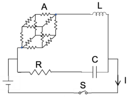
Now, the switch S is turned on at t=0 . The earliest time at which the current reaches a steady value \(I_0\) is
(a)
zero
(b)
100 \(\mu\)s
(c)
200 \(\mu\)s
(d)
infinite
Check Answer
Option a
Q.No:18 TIFR-2023
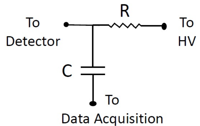
In an experiment setup, positively charged particle are detected by a detector which requires a negative DC high voltage of \(-2000\) V. Every time a charged particle is detected by the detector, it gives a transient pulse of height 10 mV.
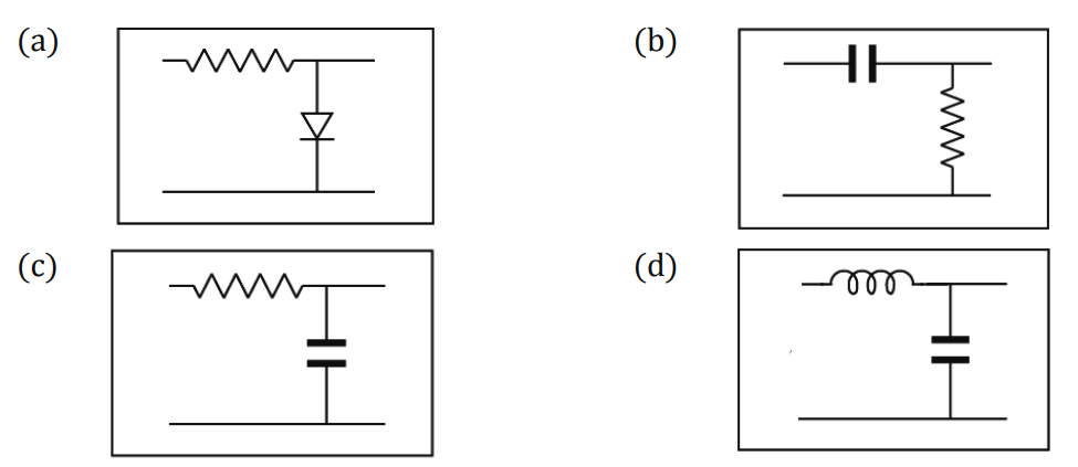
The data collection system used for the experiment needs to detect this pulse; however, it cannot operate at \(-2000\) V. Which of the following circuits can be used to connect the data collection system to the detector to obtain these pulses?